DIY If it isn't documented, it isn't made
Compilation of Sieg SX3 DRO Installations
It never seizes to amaze me how its possible to find inspiration in improving on even the simplest of tasks just by seeing what other people have done. This post is curated compilation the notes I collected when planning the DRO installation (X-axis and Y-axis) on my Sieg SX3 mill.
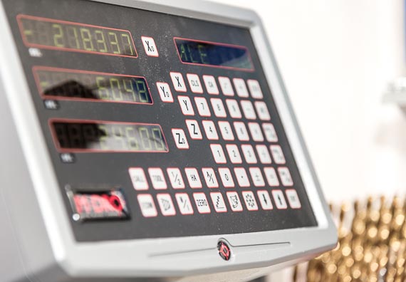
3-axis DRO unit for mill and lathe. It supports all the usual math operations, bolt circles, etc.
Almost all my projects include countless hours spent researching forums, blogs, and Youtube videos for prior art, to see what solutions other people have come up with to similar problems. If we all were to re-invent the wheel every time we started a new project, we would spend a lot of time not progressing.
From a commercial perspective this research is invaluable in identifying risks involved in the project such as spotting pitfalls upfront, assessing the machining operations involved, verifying that all tooling is available, and difficulties in sourcing materials and components.
A new project always starts out as a single document with notes, links to articles, small lists of requirements and specifications, etc. I use http://www.evernote.com/, there are countless other alternatives.
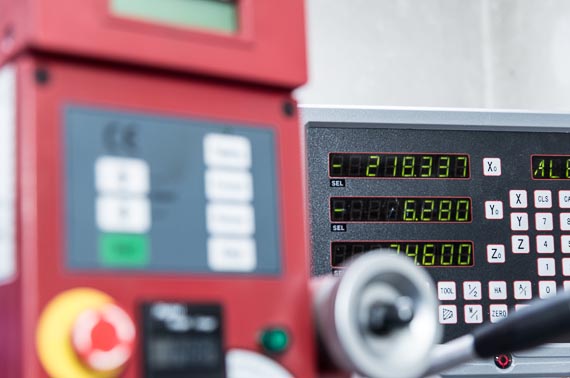
Sieg SX3 fitted with 3-axis DRO. The Sieg SX3 comes with an integrated DRO on the quill.
Build Logs
- Fitting a DRO to a Sieg X3by HMEM
- Adding DRO to my Grizzly G0463by Yuriy's Toys
- Installation - DRO Prosby DRO Pros
- SX3 DRO Installby metworx
- DROs for the Super X3 Millby mini-lathe.com
- How To Install A Magnetic DRO Kit Onto A Mill Part 1 and Part 2by DRO Pros
Fortunately for anyone planning to DRO a mill or a lathe, the companies selling DRO kits and components, invest a lot of effort in making a DRO installation accessible. Just take a look as the video collection by DRO Pros on Youtube.
DRO Kits, Supplies, etc.
New Lathe, The Wabeco D4000E
There are many different versions of the mini lathe, and they are sold in great numbers. This mini lathe is different.
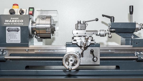
It's "Made in Germany", it's 8x14 capacity is slightly larger than the typical 7x11 mini lathe, at 80 kg it weighs almost twice as much as a small mini lathe, it has more than twice the horsepower, and it has just perfect fit and finish. It's the Wabeco D4000E.
Here, in Europe, it's only about twice the cost of a decent quality "import" mini lathe, such as the Opti D 180x300 Vario, but with that additional €1000 comes all of the above: Increased work capacity, twice the horsepower, much much lower low rpm (30 vs 150), and perfect fit and finish. And, most important of all when running a business, no need to spend a full working day or more cleaning and tweaking it to get an actual working machine.
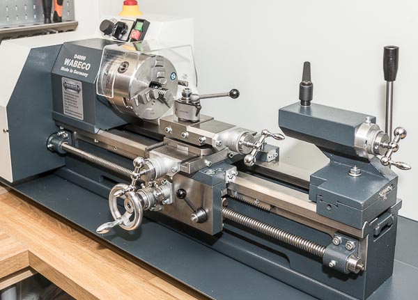
Many will also rightly claim that this is still just a flyweight lathe that isn't capable of any serious work. And that's entirely true, but for my prototype shop I only ever need turn things that are 25mm/1" OD, and no more than 10-15cm/4-5" long. And for that it seems just perfect :-)
The 5000rpm of it's significant older brother, the D6000HS, would have been very nice for improved surface finish in aluminium, but not nearly enough to justify the 2x in cost for the D6000HS when much the same result can often be achieved with a piece emery cloth.
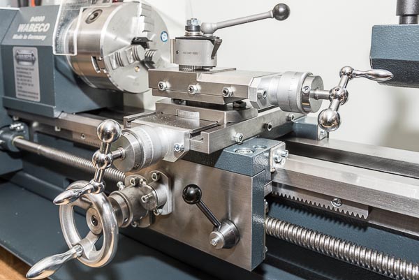
It has a 20mm spindle bore, and here is shown fitted with the 5" 3-jaw chuck it came with. I used this for my initial tests of the lathe, and have been very satisfied with it. For a Chinese 3-jaw chuck it has very little run-out.
Unlike the lathe, the chuck is not "Made in Germany". Wabeco manufactures their lathes and mills in Germany, but the accessories are imported from the East. The quality is still very nice, and easily surpasses what I have seen from e.g. Vertex.
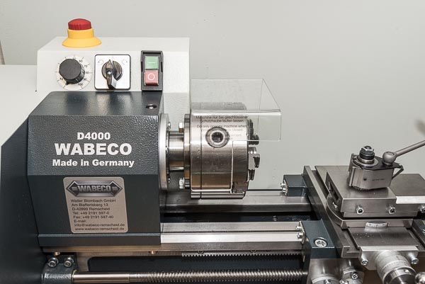
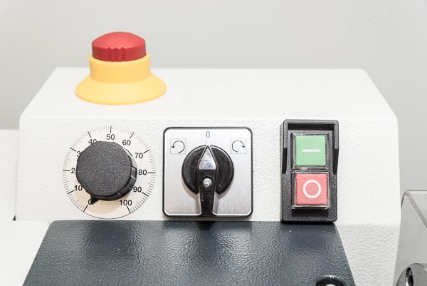
The controls are about as basic as can be. On/off switch with emergency stop, switch to select direction of turning, and electronically variable speed 30-2300rpm.
For better or worse, it uses change gears for the rest: High/low gear, screw cutting (0.25-7.0mm), and longitudinal feed rate (0.085mm and 0.16mm).
To maintain productivity, I usually plan the work so threading operations can be done with taps and dies if at all possible. All my work is built new, so I don't have to deal with strange thread pitches. I keep everything strictly metric, with the annoying exception of prototypes for optical equipment. Tripod-mounts, etc., are imperial — but there's a tap and die for that, also.
DRO Mount (X-axis) on Sieg SX3
Previous Posts
Introduction
This is the second part of my DRO installation my Sieg SX3. As stated before, there are many posts about DRO installation on a bench-top mill. This is yet another one.
I decided to start with the Y-axis since that seemed easier than the X-axis, and while the X-axis wasn't difficult it did require some additional operations, namely it required a chip shield which I had to make, since none was supplied with the DRO kit.
Installation
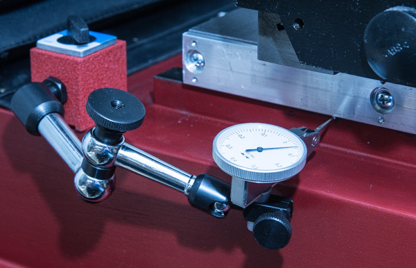
A dial indicator was used to level the aluminum profile holding the magnetic tape in relation to the saddle of the Y-axis. This is necessary since the bracket holding the magnetic encoder will be mounted on this Y-axis saddle.
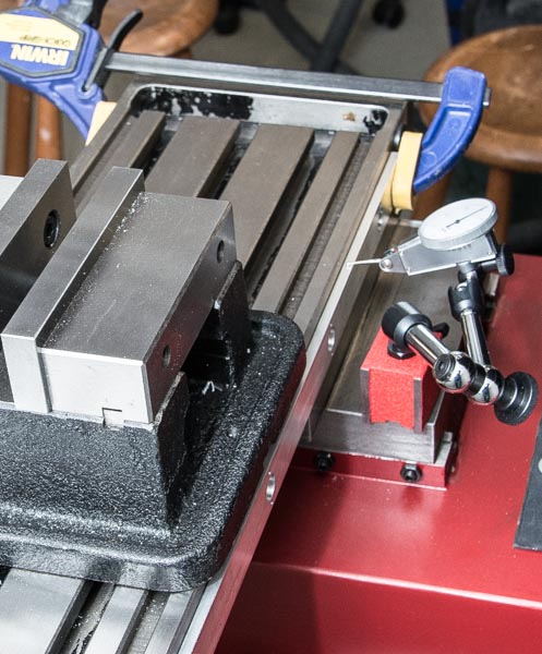
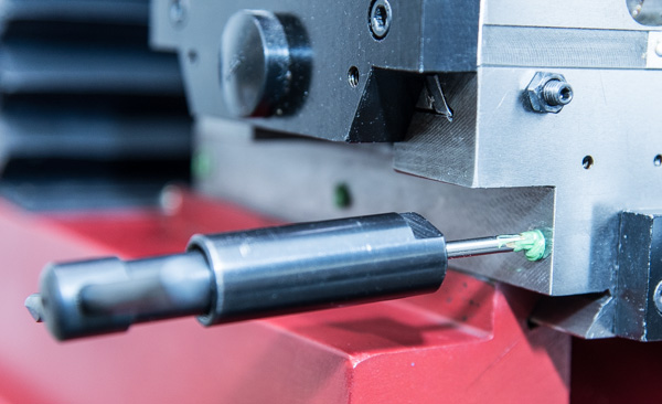
The hole locations on the aluminum profile were then transferred to the side of the mill table, using hole punches. It's just so that the ID of the recess for the screw head in the aluminum profile just fits an Ø13mm hole punch. Since this part of the aluminum profile is 4mm thick, it provides some guidance for the hole punch which would otherwise have to be aligned using only visual locating.
As it was, all 6 holes transferred accurate enough that I didn't have to enlarge any of the mounting holes in the aluminum profile.
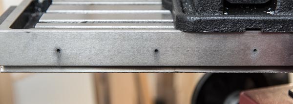
After the holes were transferred to the side of the mill table, it was the usual process of drilling and tapping the holes to receive M4 screws.
For mounting the encoder to the Y-axis saddle, an aluminum bracket was made, similar to the one I used for the Y-axis installation. The bracket probably should be a stiffer design, than just the 20x50mm aluminum angle I had at hand. The is mounted at the very edge of the long side of the bracket, so vibrations may affect the distance (gap) between the encoder head and the scale. Likewise, everyday physical abuse may bent the bracket, e.g., a bump from a heavy object.
I decided to chance it, since I reasoned I can always replace the bracket with a more, and I really needed to get the X-axis DRO going. So far it has been working great, and I haven't noticed any problems.
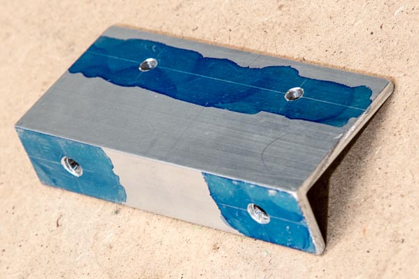
The following are close-up views of the magnetic encoder mounted on the bracket, mounted on the Y-axis saddle. The bracket was mounted using two M5 cap screws and locking washers.
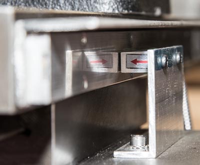 | 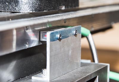 |
I chose to mount a chip shield on the X-axis to protect the scale from chips and coolant. For the Y-axis I opted not to do so, since I reasoned, the encoder head was so well protected by the table itself. The encoder head on the X-axis is located pretty much where it all happens, so I think a chip shield here is paramount.
My first inclination was to mount a simple aluminum angle bracket in the full length of the scale. However, I decided not to take that approach since a 1mm or 1.5mm thick aluminum angle just didn't seemed adequately robust. My 4" mill vice set down at an angle could easily bent it or give it a sizable dent.
Instead I selected to use 30x30x3mm stainless angle steel. I would have preferred to use 40x40 or 50x50, but that doesn't fit on the side of the mill table so that would require taking 10mm off the full length of one side, and the extra 10mm overhang just didn't seem to justify that operation.
The dimensions of angle steel are different from aluminum angle. The aluminum angle is basically two sides joined at 90 degree angle, which can be seen on the bracket that is used to mount the encoder. Angle steel is shaped to give it better structural strength, which means the sides are slanted, and there's an inner radius where the two sides are joined. The inner radius prevented the scale from mounting flush to the side of the angle steel, as can be seen in this before-after picture.
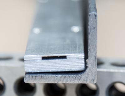 | 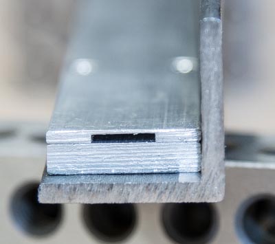 |
I hoped that removing the slant on the side where the scale would be mounted wasn't necessary for proper operation, since that would have been a fairly time consuming operation with my SX3, given the length of the angle.
The inner radius was pretty easy to remove. I didn't really need to hold any specific tolerances, I just needed the scale to mount flush with the side. So I just fixed the angle steel on two parallels in the vice, and eyeballed the cut. The vice supported 4" of the bracket, and I could continue the cut out about another 2" inches unsupported, so by cutting first from one end of the angle and then from the other, I was able to remove the radius from the full length of the angle.
After that, mounting holes corresponding to mounting holes in the aluminum profile were drilled. The holes were drilled to provide good clearance for the screws.
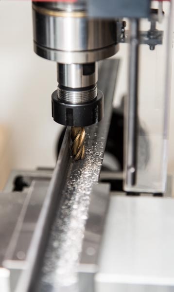 | 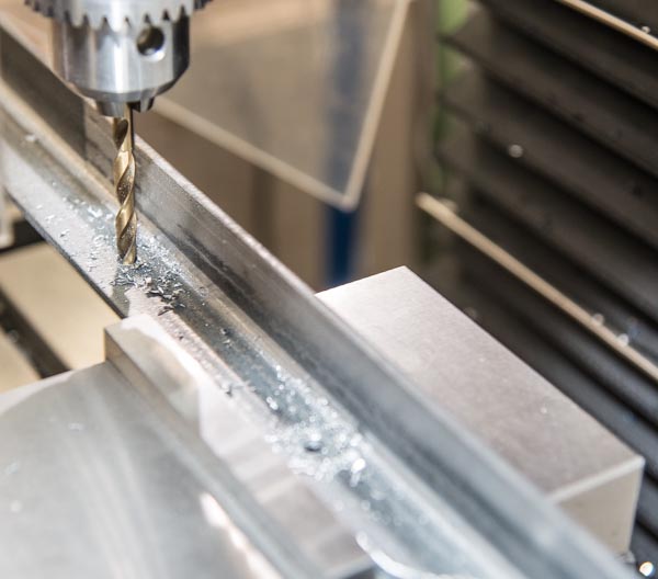 |
The slant is easily visible in a close up of the installed scale, and also in the gap between the encoder and the scale. The scale could be shimmed in the mount on the angle, but in practice this offset from parallel hasn't been an issue.
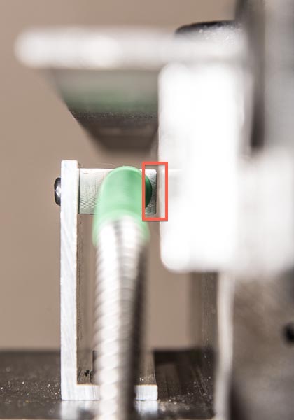
And this is what the full thing looks like :-)
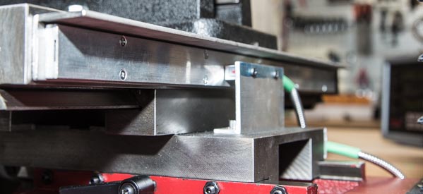
I do still think the encoder head seems a little "out in the open". But so far no chips have found their way into the gap or even just onto the encoder head.
This is the top view.

Awesome, Inexpensive, Machine Tool Light
A high output, totally flexible, machine tool light, that costs only $50, and can be built and mounted in 15 minutes.
Seems too good to be true, but after I have been through a number of iterations on improving lighting on my mill, that is what I ended up with.
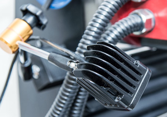
Background
When I got my Sieg SX3 I first mounted a small goose neck lamp with a 14W halogen reflector spot in an E14 mount. This worked fairly well, but didn't quite deliver enough illumination, and the emitted infrared heat from the lamp has annoying when working close to the lamp. Also, during extended periods, the lamp became fairly hot to the touch, so care had to be exerted not to touch the lamp. In short, a decent solution but with room for improvement.
Next up, was a small 3W LED lamp with a long goose neck. This lamp output less lumens than the first solution, but in a more tightly focused beam, and with the longer goose neck and smaller lamp head, it was easier to manoeuvre into place to provide the illumination where it was actually needed in relation to a specific cut, and avoid unwanted shadows. Given the low wattage emitted and built up heat was not an issue.
Both attempts were hastily put together to provide just some kind of illumination close to the spindle. I finally decided I needed to improve this, since I find proper illumination to make a huge difference in my work.
By chance I found some cool looking 10W and up LED lamps meant as work lights on tractors, trucks, ATVs, etc., and they seemed to be perfectly suited for this task:
- High lumens output
- Selection of flood or spot light
- Sealed to IP67 to provide good protection from "the elements". Here, that would be chips, coolant, etc.
- Efficiency comparable to compact fluorescent lamps, which watt-to-watt is a 2x improvement over halogen bulbs.
- It can be powered from any number of "wall warts" I already had lying around
Next up, I needed a flexible way of mounting the LED lamp on the mill (and other machine tools). The goose necks from my previous attempts were not going to carry the weight of the LED lamp head, so a different solution with the same manoeuvrability was needed.
I ended up with a universal magnetic stand for a dial indicator. The reach of the arm was somewhat less than I had hoped for, but other than that it seemed like the perfect solution:
- The magnetic base provided great freedom of placement on the mill (or any other machine tool), and plenty of holding force
- The single locking mechanism on the arm, made it a comfortable two-hand operation to position the lamp head and lock it into place. No wishing for a third hand.
- It was cheap
Built
This is the BOM I ended up with:
- LED lamp ($20)
- An M4 stainless cap screw bolt
- Two M4 washers
- An M4 nut to go on the bolt
- Universal magnetic stand ($30)
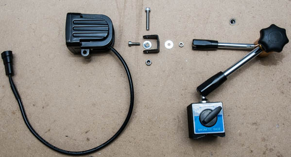
And this is what the kit looks like put together. I opted for a flood beam LED light, because I only have a small mill and the lamp head will be mounted in close proximity to the spindle. For larger machines or other situations where the lamp head is mounted further away from the action, I would recommend a spot beam shape.
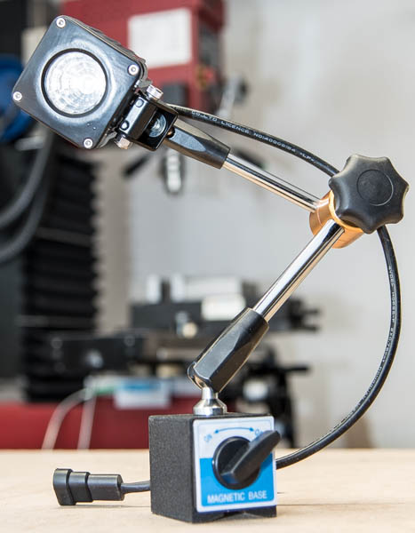
I'm going to add a spot beam lamp to my setup, and move the flood lamp a little further away, to get good overall lighting of the work area, and concentrated illumination of the cutting action.
It is difficult to capture the level of light provided by the lamp. The dynamic range of this on-screen image is much less than what the human eye can discern, and is generally limited with the color depth of the display or print technology.
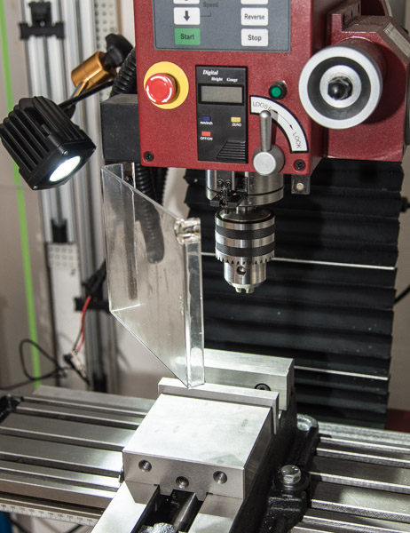
I do think this image captures the provided illumination fairly well, in relation to the overall lighting of the surroundings in my workshop, which is already very well illuminated with white walls and ceilings, and 200W of installed fluorescent overhead lighting in an area of just 12 m2.
DRO Mount (Y-axis) on Sieg SX3
There are many posts about DRO installation on a bench top mill. This is yet another one.
This post details how I installed DRO on the Y-axis of my Sieg SX3. Unlike most other builds I've seen, I elected to use magnetic tape, instead of the usual plunger- or optical scales.
Magnetic tape and encoder has several advantages over optical scales (which in turn are better than plungers):
- The magnetic tape mounted in an aluminium profile is much more robust than an optical scale
- Both scale and encoder head are fully sealed to IP67 which makes them much more resilient to the harsh environment on a mill
- The required aluminium profile and magnetic encoder head are much smaller than a comparable optical system, making them easer to fit in tight spaces
Since I live in Denmark, the selection of readily available DRO systems is much smaller than in the states. I selected a system from Allendale Electronics Ltd., and they provided excellent support on selecting suitable components for my specific mill.
Of course this comes at a price, and a full DRO system using magnetic tape and encoders is around 20% more expensive than a comparable system using optical scales. Also, while the magnetic encoders have a resolution of 1 micron (0.001mm), their accuracy is only +/- 0.015mm whereas typical optical encoders have an accuracy of +/- 0.005mm, and this may be a deal breaker for some.
I doubt the Sieg SX3 is capable of repeatedly working to such tolerances, and the temperature variations in my workshop are certainly much too great for that level of accuracy. Also, the prototypes I make usually only need to hold "look good" tolerances, typically within 0.08-0.1mm. So, I prioritised the practical benefits of a system based on magnetic encoders, and I've been very happy with it so far.
Installation
Using a dial indicator to level the aluminium profile holding the magnetic tape.
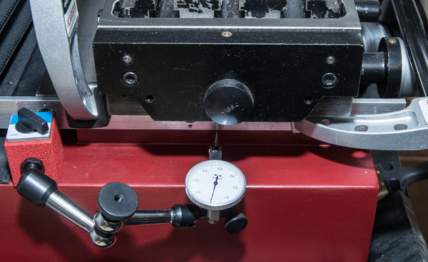
The mounting holes in the aluminium profile was used to transfer the hole locations to the Y-axis saddle. The holes in the aluminium profile has recessed hole for the screw heads. The OD of a 13mm hole transfer punch fits perfectly in this recess.
The transferred holes are then drilled to Ø3.2mm.
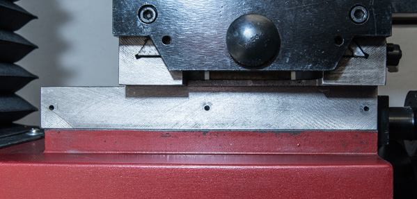
The drilled holes are tapped with an M4 tap. There was no room for a tap guide, and an M4 tap is easy to snap, so I used a new taps, separate rougher, intermediate, and finisher taps, and plenty of cutting paste to prevent tap breakage. The Y-axis saddle is cast iron which is actually very easy to tap, and yields very clean and well defined threads.
This is a test mount to check for fit of the aluminium profile. As can be seen, it has not been cut to size yet. The extrusion is mounted with M4 screws, but the pre-cut holes in the profile are Ø6mm, so they allow for plenty of play to compensate for off-centre mounting holes, and any fine adjustments to level the extrusion.
I used the Y-axis saddle as guide to scribe lines where the profile will be cut to length.
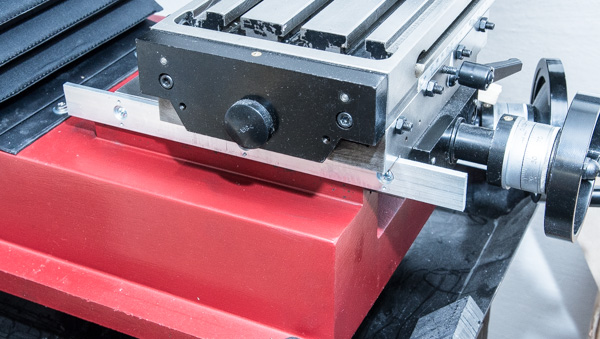
After the profile is cut to length, the dial indicator setup is again used to level the profile on the Y-axis saddle.
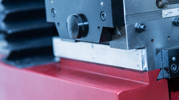
The profile mounted with cover holding the magnetic tape.
Next, a bracket is made, that will hold the magnetic encoder head. It is just a simple aluminium angle bracket with 4 holes. Two for mounting to the mill base, and two for holding the encoder head.

The bracket was used to again transfer the hole locations to the mill base using a hole punch. The angle bracket does not provide a very good guide for the hole punch, so afterwards it was necessary to shape the mounting holes in the bracket with a needle file. Slightly annoying, but it has no practical implications.
After the holes were transferred they were drilled with Ø4.3mm and tapped using M5 rougher, intermediate, and finisher taps. The mill base cast is only about 12mm thick, so it was an easy through-hole tap, even though there wasn't room for a tapping guide.
In retrospect, I could easily have used a finisher tap directly, since the cast iron is very easy to cut, and a broken tap would have been easy to remove. However, I approach all modifications I make on existing (=expensive) equipment as one-shot-only, and so I take the long approach of tap forming.
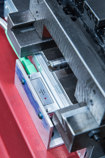
Here, the bracket is mounted and the magnetic encoder head is installed on the bracket. Clearance between the encoder head and the profile must be between 0.1-1.00mm, so I used a 0.5mm feeler gauge to set the distance.
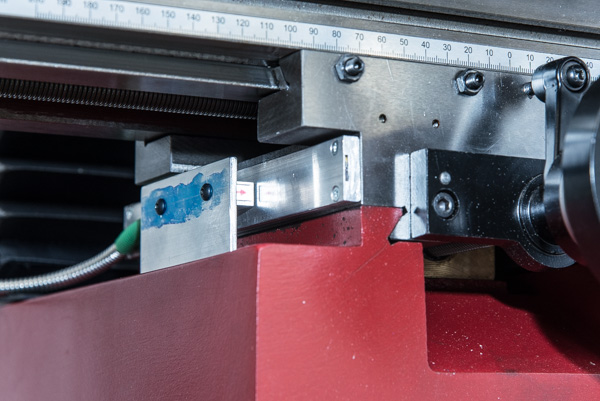
A different view of the final installation. I find that the magnetic tape and encoder gives a very clean and tight installation. It avoids the extensive angle bracket and mounting on the side of the mill base, and it employes the mill table as a natural chip shield.
The magnetic tape is impervious to coolant and chips, and the encoder head itself is protected to IP67 so in principal, a chip shield is not necessary. However, I think that chips could easily get stuck in the tight clearance between the encoder head and profile holding the magnetic tape, and so I believe that a chip shield is still necessary.
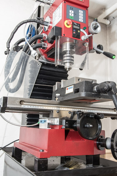
And this is what the full thing looks like :-)
Awesome Video From A Modern Day Blacksmith
I usually don't subscribe to Youtube channels. AWE me is one of the rare exceptions, and the only reason is to track the truly amazing creations from Tony Swatton of Sword and the Stone.
Every week he posts a video showing the creation of a sword. The videos are short (< 10min), concise, and of great quality being produced by a professional production company. The videos are not detailed walkthroughs of the processes involved. Rather they are motion picture presentations of the creation with much emphasis on the entertainment value. Which is wholly fine with me. Definitely worth my precious time.
The craftsmanship, quality, and attention to detail that is shown is truly amazing.
Excellent Article On How Photographic Lenses Are Manufactured
I've always been very fond of detailed and illustrated descriptions of how different manufacturing processes work. The show "How It's Made" has always been a favourite of mine.
Being very interested in photography, I read a lot of photo related web sites, and came across this excellent article on Imaging Resource on how photographic lenses are made.
It provides a good commentary with a lots of excellent close-ups of the complex machinery involved in the mostly automated manufacturing processes to produce the lenses that Sigma sells.
This manufacturing process is interesting, in that it also involves machining glass. Most articles and Youtube videos , etc., are about machining different kinds of metals so the challenges involved in machining glass is a nice addition. Take a look at this grinder:
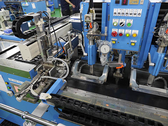
(credit: Imaging Ressource)
An Improved Pellet Trap (part 2): Design
Previous Posts
Design
The design of the pellet trap I'm building is fairly simple, using a combination of friction and impact to stop pellets. First, a replaceable layer of 3mm PVC plastic will use friction to decelerate the pellets, and then two layers of 12mm polyurethane (PUR) sheet will use impact to stop the pellets.
I'm fairly happy with this design, as it meets most of my design goals:
- It's low maintenance. The PVC sheet will need replacing from time to time, but not too often. The PUR sheet should last a very very long time, especially when using wad cutters at no more than 12J.
- It's quiet. The impact with the PVC sheet will be audible, but much less so than most other materials like wood, hard plastic, or steel.
- It's cheap. Only small amounts of PVC and PUR sheet is required, and the cost per m2 of these materials is low.
The one property of the design that I'm not too happy about is, that PVC and PUR sheet is fairly difficult to come by in the small quantities required - and whole reel of PVC does cost a lot of money. Patches of conveyer belt can work just as well as PUR, so depending on your geographical location, this may be easier to come by. I have yet to find an alternative to PVC.
The main advantages of PVC is that it heals (closes) really well and that no material is "removed" on pellet strike. No other materials I've looked at close anywhere near as good and they leave a big mess. Common materials used such as patches of carpet, news paper, phonebooks, and cloth, they don't "close" the whole after a pellet strikes (carpet and cloth does to a limited extent) and over time they make a mess from the trace materials they leave on pellet strike.
Background
Bullet traps in general are based on one of three principles:
- Impact
- Friction
- Deceleration
Impact and friction designs are much simpler than a deceleration design, and maybe as a consequence, no commercially sold pellet trap is based on this design. A pellet carry much less energy than a bullet fired from a firearm, and is thus much easier to stop, which also detracts from using a deceleration design.
Because of the inherent "klang" from a pellet trap based on an impact design, I decided the design also needed to incorporate a friction element, to reduce the energy of the final impact strike. With a deceleration design, there will still be a pellet strike, and probably also a "klang".
Many people are reporting that the "klang" from most pellet traps can effectively be suppressed using some form of moderator (cloth, foam, insulation, etc.), however there is still the risk of lead dust to consider.
Friction style bullet traps, in general, are typically based on one of the following designs:
- Sand berm
- Rubber berm (same as sand berm, but using rubber granule)
- Sheets of material
The sand berm is a fantastic engineering solution. Cheap, very effective, and "self-reorganizing" so it overcomes the inherent problem of concentrated high energy impacts. Use of rubber granule was inspired by the sand berm. A material was needed that had the same properties as sand, but made separating material from bullets easier.
Action Target has made a very good analysis of berms made from rubber granule (original link) and local copy.
The US Army also did an extensive study on commercially sold bullet traps, and it's an excellent walkthrough of different design principles and the associated pros and cons. Here's the (original link through Google) as well as local copy.