DRO Mount (X-axis) on Sieg SX3
Previous Posts
Introduction
This is the second part of my DRO installation my Sieg SX3. As stated before, there are many posts about DRO installation on a bench-top mill. This is yet another one.
I decided to start with the Y-axis since that seemed easier than the X-axis, and while the X-axis wasn't difficult it did require some additional operations, namely it required a chip shield which I had to make, since none was supplied with the DRO kit.
Installation
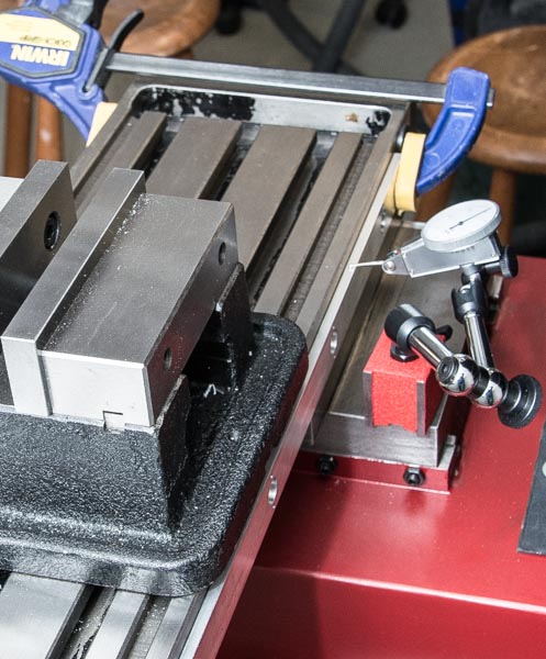
A dial indicator was used to level the aluminum profile holding the magnetic tape in relation to the saddle of the Y-axis. This is necessary since the bracket holding the magnetic encoder will be mounted on this Y-axis saddle.
The hole locations on the aluminum profile were then transferred to the side of the mill table, using hole punches. It's just so that the ID of the recess for the screw head in the aluminum profile just fits an Ø13mm hole punch. Since this part of the aluminum profile is 4mm thick, it provides some guidance for the hole punch which would otherwise have to be aligned using only visual locating.
As it was, all 6 holes transferred accurate enough that I didn't have to enlarge any of the mounting holes in the aluminum profile.
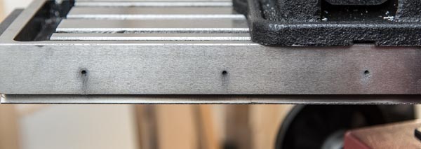
After the holes were transferred to the side of the mill table, it was the usual process of drilling and tapping the holes to receive M4 screws.
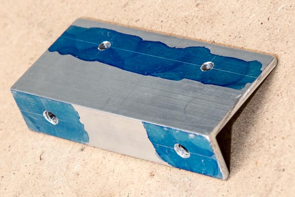
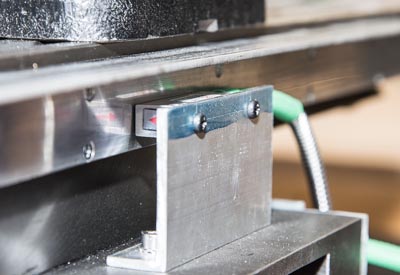
For mounting the encoder to the Y-axis saddle, an aluminum bracket was made, similar to the one I used for the Y-axis installation. The bracket probably should be a stiffer design, than just the 20x50mm aluminum angle I had at hand. The is mounted at the very edge of the long side of the bracket, so vibrations may affect the distance (gap) between the encoder head and the scale. Likewise, everyday physical abuse may bent the bracket, e.g., a bump from a heavy object.
I decided to chance it, since I reasoned I can always replace the bracket with a more, and I really needed to get the X-axis DRO going. So far it has been working great, and I haven't noticed any problems.
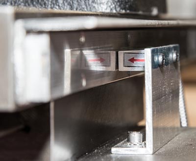
The following are close-up views of the magnetic encoder mounted on the bracket, mounted on the Y-axis saddle. The bracket was mounted using two M5 cap screws and locking washers.
 |  |
I chose to mount a chip shield on the X-axis to protect the scale from chips and coolant. For the Y-axis I opted not to do so, since I reasoned, the encoder head was so well protected by the table itself. The encoder head on the X-axis is located pretty much where it all happens, so I think a chip shield here is paramount.
My first inclination was to mount a simple aluminum angle bracket in the full length of the scale. However, I decided not to take that approach since a 1mm or 1.5mm thick aluminum angle just didn't seemed adequately robust. My 4" mill vice set down at an angle could easily bent it or give it a sizable dent.
Instead I selected to use 30x30x3mm stainless angle steel. I would have preferred to use 40x40 or 50x50, but that doesn't fit on the side of the mill table so that would require taking 10mm off the full length of one side, and the extra 10mm overhang just didn't seem to justify that operation.
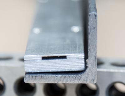
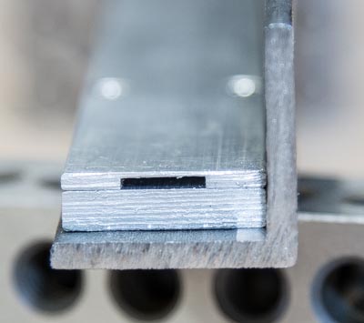
The dimensions of angle steel are different from aluminum angle. The aluminum angle is basically two sides joined at 90 degree angle, which can be seen on the bracket that is used to mount the encoder. Angle steel is shaped to give it better structural strength, which means the sides are slanted, and there's an inner radius where the two sides are joined. The inner radius prevented the scale from mounting flush to the side of the angle steel, as can be seen in this before-after picture.
 |  |
I hoped that removing the slant on the side where the scale would be mounted wasn't necessary for proper operation, since that would have been a fairly time consuming operation with my SX3, given the length of the angle.
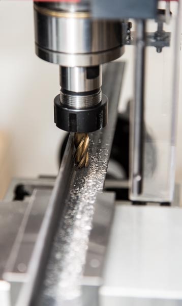
The inner radius was pretty easy to remove. I didn't really need to hold any specific tolerances, I just needed the scale to mount flush with the side. So I just fixed the angle steel on two parallels in the vice, and eyeballed the cut. The vice supported 4" of the bracket, and I could continue the cut out about another 2" inches unsupported, so by cutting first from one end of the angle and then from the other, I was able to remove the radius from the full length of the angle.
After that, mounting holes corresponding to mounting holes in the aluminum profile were drilled. The holes were drilled to provide good clearance for the screws.
 | 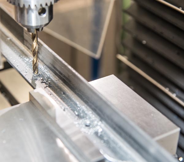 |
The slant is easily visible in a close up of the installed scale, and also in the gap between the encoder and the scale. The scale could be shimmed in the mount on the angle, but in practice this offset from parallel hasn't been an issue.
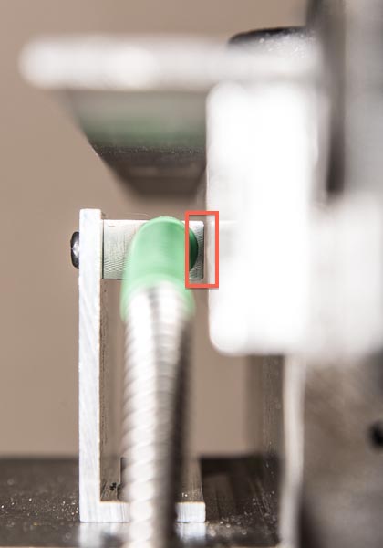
And this is what the full thing looks like :-)
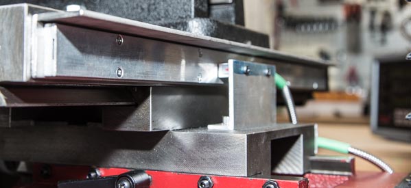
I do still think the encoder head seems a little "out in the open". But so far no chips have found their way into the gap or even just onto the encoder head.
This is the top view.

blog comments powered by Disqus
Published
Tags
Related Posts
- DRO Mount (Y-axis) on Sieg SX3
- Choosing A Mill
- Awesome, Inexpensive, Machine Tool Light
- Z-axis Bellows Mount (Part 2): Top Bracket
- Simple Color Response Test (Method & Results)