Z-axis Bellows Mount (Part 2): Top Bracket
Previous Posts
Started Work On A Z-axis Bellows Mount
Top Bracket
The top bracket is made of two pieces of aluminum. A smaller bar that holds three magnets, and fixes to the milling head between the tilting head mount and the vertical column, and a wider plate screwed to this bar and to which the top part of the bellows is attached.
First step in making the small part of the top bracket is to cut a piece of aluminum 20x15x140mm. I used 6082 but any alloy will do.
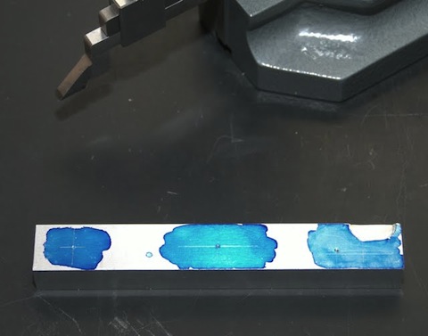
Layout scribe marks for drilling the holes for the magnets.
Note that the right mark is off center from the other two marks to make room for the bottom screw securing the z-axis gib. Also, a small recess for the screw head has been milled in the top right corner of the aluminum bar.

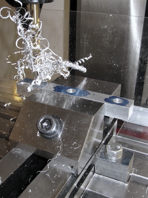
Drilling holes for the magnets in the small bar.
The magnets are round measuring 10mm in diameter and 10mm in length. They will be press fitted in the top bar so the holes are drilled using a 9,9mm drill.
The finish and hole concentricity doesn't really matter in this case, so I didn't bother center drilling or gradually opening up the hole size. I drilled directly to size using plenty of WD-40. The downside to this approach, as can be seen in the image, is the tangle of aluminum swarf.
The max spindle speed of the SX3 is 1800rpm which is not nearly enough to break the chips in drilling operations.

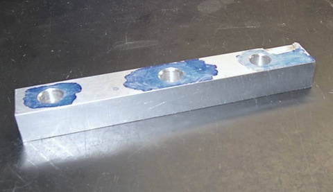
The finished piece that will hold the magnets in the top bracket.
Each magnet yields a 6,5kg pull, and it remains to be seen if this is adequate to keep the bracket in place when the bellows is fully extended.

In part 3, I'll cover making the bottom bracket ...
blog comments powered by Disqus
Published
Tags
Related Posts
- DRO Mount (Y-axis) on Sieg SX3
- Z-axis Bellows Mount (Part 3): Bottom Bracket
- DRO Mount (X-axis) on Sieg SX3
- Choosing A Mill
- Z-axis Bellows Mount (Part 1): Introduction