DIY If it isn't documented, it isn't made
An Improved Pellet Trap (part 1): Reasoning
When I recently needed an airgun pellet trap for practicing concentration and trigger pull indoors, I expected that a Google search would make quick work of a workable solution. Not so!
I had devised a list of functional- and non-functional requirements:
Functional requirements
- Pellet sizes: 4,5mm (0.177) and 5,5mm
- Pellet shapes: Flat and domed
- Pellet energy design envelope: < 16J (12FPE)
- Pellet energy safety envelope: < 50J
- Expected range: 0-10m
Non-functional requirements
- Can be used indoors
- Quiet
- Free of lead dust
- Small, light, and portable
- Easy to clean spent pellets
- Low maintenance
- Cheap in use
A pellet trap poses an interesting engineering challenge: Absorbing thousands of concentrated high energy impacts.
An angled steel plate is a seemingly perfect solution: Simple, cheap, effective, easy to make. Unfortunately, it produces lead dust at impact speeds surpassing 200m/s, so indoor use really is limited to low power air guns. And, even worse, there is that never ending "klang" on pellet impact. That significantly reduces the WAF factor :-)
Another, maybe even more seemingly perfect solution, has been devised: The sand berm.
In addition to all the qualities of the angled steel plate, it's a beatiful engineering solution to the problem of absorbing concentrated impacts: It self organizes. Unfortunately, a sand berm takes up a lot of room. It doesn't take a lot to stop an airgun pellet, but to have an acceptable height, it needs to be big. An then there's the whole mess of having it indoors.
It quickly became apparent, that all pellet traps being sold are in some way based on an angled steel plate, and so a different solution had to be sought.
The go-to solution for an improved pellet trap seems to be variations on the "Silent" Pellet Trap. In addition to being simple, effective, and easy to make, it's also quiet and free of lead dust. It seems perfect.
Unfortunately, the magic ingreedient in that solution - Duct Seal - is far from cheap in Denmark where I live. The 6kg which a pellet trap with duct seal typically requires, is almost $200 here :-(
So, instead I decided to build an improved pellet trap that would satisfy my requirements.
Dial Indicator
A dial test indicator is used for so many things, that listing them all doesn't make sense. For example, accurately squaring your milling vice without one is next to impossible. And starting around €25 it's one of the first accessories you should buy.
The cheap Chinese versions are typically sold in a kit with a magnetic stand. Do get such a kit, because it's cheap and because the stand is nice to have for other things. But instead of using the dial test indicator with the magnetic stand, get an Indicol holder and mount it in that.
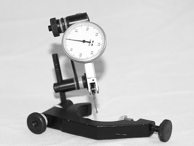
The Indicol holder makes it easy to attach the dial test indicator to just about any tool holder mounted in the mill spindle, and this arrangement is by far the best way to square a milling vice to the table and tram the mill column. Those two applications alone, make the Indicol holder worth getting, but it has numerous other uses.
And it's cheap! Just €15 ($20) for the Indicol holder, which really makes me wonder why there are no kits including one of these.
Dial test indicators have a swivel lever arm, whereas a dial indicator has a plunge lever. I find more different uses for the dial test indicator and so my recommendation would be to get one of those before you get a dial indicator. However, in setups they are interchangeable and so personal preference comes into play.
An excellent resource for everything related to dial indicators is Long Island Indicator Service that specialize in servicing [quality] dial indicators. Dial indicators are high precision mechanical instruments that need maintenance, and the high cost warrant repairs rather than replacements. Their focus is obviously on quality indicators, and not the cheap Chinese tools, but they have a lot of good information, and since a "quality" dial test indicator starts at €130 ($170), it's one of the accessories where many will opt for the "real thing".
Simple Color Response Test (Method & Results)
I'm researching application of white LED's as a replacement for interior lightning, and as part of that I need to answer two qualitative parameters:
- How many lumens of LED light is needed to replace an 11W CFL bulb and a 20W halogen spot
- Is the color response of LED's acceptable (and where isn't it)
This small test is my initial effort to address the latter. This test has three purposes:
- Demonstrate the viability of the testing method
- Indication of color response for two different white LED's
- Indication of color response for fluorescent tubes and CFL bulb
With a background in computer science and electrical engineering, I have no theoretical foundation to base my tests on, and the perception of color response is very subjective (just look at some of the threads on Candlepowerforums). The purpose of this test is not to give authoritative statements on applicability of specific lighting technologies, but to find something I like to look at every day. I've always favored cold color temperatures - even halogen light appears yellow to me, and warm white CFL appears greenish - and that, I suspect, will strongly influence my preference.
An additional area I also want to investigate is whether a mix of cold and warm white LED's produce better color response, and if so a rough indication of the ratio of emitters. I realize that mixing red emitters with cold white emitters is probably a better strategy, but my red emitters are still on their way from Hong Kong, so that test will have to wait.
Testing Method
The test was conducted by placing an IT8.7/2 target in a light box with the light source on left side of the light box. The camera was mounted on a tripod. Shutter speed was kept constant and an aperture was selected according to the light source. The camera white balance was set to 6300K, and shots were recorded in both jpg and raw.
For this test I used a reflective IT8.7 target printed on Kodak professional paper, because I had trouble fitting the bigger non-reflective A4 version in my light box. This really isn't ideal, as that IT8.7 is intended for flatbed scanners, not cameras. This would be relevant if I was to use the results to create a color response correction profile for the camera and/or light source, but in this application I don't think it makes a difference. The brain does a ton psychological "processing" anyway.
The target of this test was a cheap superflux LED (brand and type unknown) I've sourced in England. I expect them to perform much worse than a quality high power emitter from e.g. Cree or Seoul. For the LED light I wired 3x18 of the superflux LED's (2x18 cold white and 1x18 warm white), allowing ratios of 1:1 and 2:1 between cold white and warm white.
Post Processing
For this test, image post processing was done on the jpg's in Google Picasa. I'll redo the post processing in GIMP in a more controlled fashion on the RAW versions when time permits.
Two post processing steps were done:
- Images were cropped to show just the IT8 target
- Neutral point was set to the neutral grey reference on the IT8 target, to correct for difference in color temp between the light sources
I don't really know what selecting neutral point in Picasa actually does. Picasa simplifies everything so it might do some further processing I'm now aware about (hence the need to repeat in GIMP to make sure), but judging by the results it does what I expected.
Results
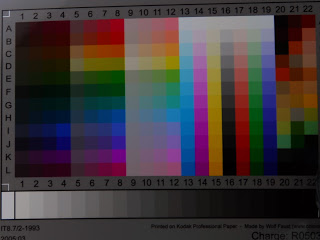
The processed images are the results: Select which one you like the most. For each image I've provided a link to the non temperature corrected version.
I haven't quite decided on a satisfactory explanation for the corrected color response of #1 and #2. If I didn't now otherwise, I'd have expected #1 to be from the warm white LED, but it's not! I've redone the test several times to make sure, and my results can easily be verified by using the non-corrected copy of the image where the color temperature of the warm white emitter is very visible. Anyone care to comment?
| 1 | 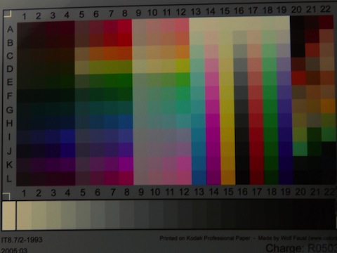 | 20100602-233520 CW Superflux LED, cold white Brand and type unknown Specifications Emitting Color: White |
| 2 | 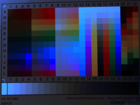 | 20100602-233620 WW Superflux LED, warm white Brand and type unknown Specifications Emitting Color: Warm White |
| 3 | 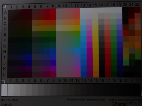 | 20100602-233706 CW:WW 1:1 Mix of #1 and #2. Ratio cold white to warm white is 1:1 |
| 4 |  | 20100602-233746 CW:WW 2:1 Mix of #1 and #2. Ratio cold white to warm white is 2:1 |
| 5 |  | 2x56W Philips T8 940 Fluorescent tubes 2x32W No-name T8 840 Fluorescent tubes The thick white line is the lower left area is glare from the fluorescent tubes, because the color reference is on glossy paper, and there was direct line of sight to one tube mounted in the ceiling. |
| 6 | 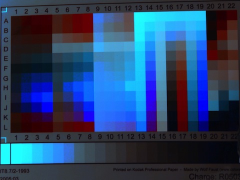 | 20100602-234239 WW CFL Cheap no-name low energy bulb |
Z-axis Bellows Mount (Part 3): Bottom Bracket
Previous Posts
Started Work On A Z-axis Bellows Mount
Bottom Bracket
I made the bottom bracket from a single piece of aluminum measuring 75x235x15mm. In this a slot for the Z-axis way is cut and holes are drilled in the bottom for press fitting the magnets that will fix the bracket to the mill base.
Cutting a piece 240mm long from existing bar stock. Even with a brand new bi-metal blade and plenty of WD-40 that is still quite a chore. Time to start saving for that band saw!
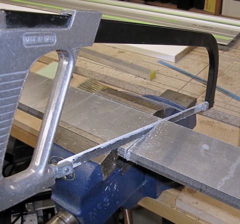
Squaring the edges of the sawed of piece. Another downside to using a manual hack saw is that the saw cut tends to be quite at quite an angle from vertical, hence the need to remove a lot of material before the edge is square.
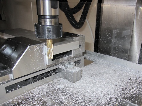
Here I'm using a 10mm 4-flute end mill where the end is damaged. It's certainly not ideal for this type of operation, but squaring ends is purely for cosmetic reasons - the finish and dimensions of the edges are in no way critical - so I decided to save the wear on my other end mills for more critical applications.
In part 4, I'll cover making the bottom bracket ...
Simple Color Response Test
This had been on my todo list for a long time. A comparison of the color response of different light sources.
Incandescent light bulbs have a color rendering index (CRI) of 100 whereas most artificial light sources have a CRI of 70-80, and even "high CRI" versions of artificial light sources only reach CRI values of 90-95. I'm making LED fixtures for a number of lamps around the house, and so I have been interested in finding out what the lower CRI values actually means in terms of color response,
I used an IT8 target as my reference. An IT8 target, is a color reference used to calibrate the color profiles of digital imaging equipment such as digital cameras and scanners. The sensors and optical filters in digital imaging equipment is more sensitive to certain colors, and so a calibrated color reference photo is used to compensate for this non-linearity.
This characteristic of color imaging equipment is very much similar to the behaviour of artificial light sources that often emit much more light at certain wave lengths (as does fluorescent tubes) or certain bands of wave lengths.
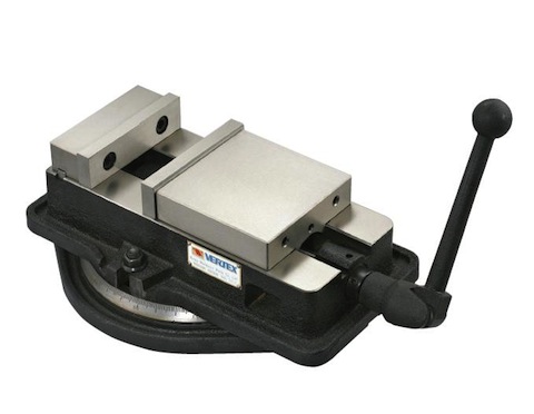
Vertex VA-4 Finally Arrived
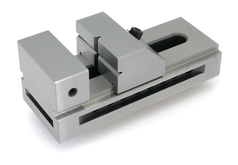
Ever since the SX3 arrived, I've been wanting a real milling vice. My 80mm screwless precision vice (something like this) is adequate for small stuff, but chatter is a significant problem with it, and it shows on the finish. I've spent a lot of time searching the Internet for the best one I could afford, a finally decided on the Vertex VA-4. I've written more about the selection process here.
The VA-4 is much more massive than my precision vice and at 20kg vs 6kg for the precision vice it's a completely different weight class. I really need to make a side-by-side comparison picture to show the true difference.
The make and finish of the VA-4 is very nice for a Chinese knock-off (the "real deal" is a 4" Kurt angle-lock vice). Finish is much greater than what I've seen for other Chinese Kurt-style vices, but it's not on par with the make and finish of my screwless precision vice. My own general rule for machine tools is that you pay a standard price per kg with the actual price per kg depending on the overall quality, and at 4x the weight but only twice the cost of my screwless vice the VA-4 should be about half as nice in make and finish, and that seems about right.
Z-axis Bellows Mount (Part 2): Top Bracket
Previous Posts
Started Work On A Z-axis Bellows Mount
Top Bracket
The top bracket is made of two pieces of aluminum. A smaller bar that holds three magnets, and fixes to the milling head between the tilting head mount and the vertical column, and a wider plate screwed to this bar and to which the top part of the bellows is attached.
First step in making the small part of the top bracket is to cut a piece of aluminum 20x15x140mm. I used 6082 but any alloy will do.
Layout scribe marks for drilling the holes for the magnets.
Note that the right mark is off center from the other two marks to make room for the bottom screw securing the z-axis gib. Also, a small recess for the screw head has been milled in the top right corner of the aluminum bar.

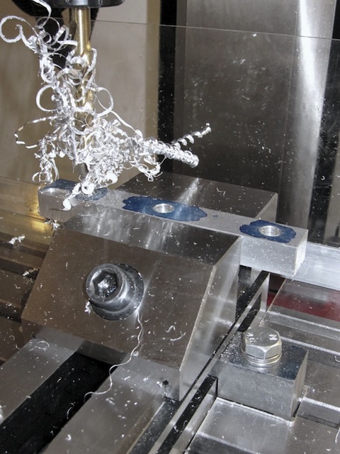
Drilling holes for the magnets in the small bar.
The magnets are round measuring 10mm in diameter and 10mm in length. They will be press fitted in the top bar so the holes are drilled using a 9,9mm drill.
The finish and hole concentricity doesn't really matter in this case, so I didn't bother center drilling or gradually opening up the hole size. I drilled directly to size using plenty of WD-40. The downside to this approach, as can be seen in the image, is the tangle of aluminum swarf.
The max spindle speed of the SX3 is 1800rpm which is not nearly enough to break the chips in drilling operations.
The finished piece that will hold the magnets in the top bracket.
Each magnet yields a 6,5kg pull, and it remains to be seen if this is adequate to keep the bracket in place when the bellows is fully extended.

What Tolerances Can You Expect
That was probably the most pressing question I wanted answered, when I got a mill. And the answer seems to be 0,01mm if your very careful.
Not the accuracy of the mill itself - I felt very sure, that straight out of the crate, the mill would be way out of tram, and that certainly was the case! Rather, given a properly trammed mill, to what tolerances should I be able to machine stuff? Give and take how many tenths, hundreds or thousandths of a millimeter should I reliably be able to produce a part of a certain length, width, or height?
Part of the answer was pretty straight forward. Commonly available - and affordable - measuring instruments (calipers, micrometers, height gauges) have a resolution of 0,01mm (digital micrometers and some dial indicators resolve to 0,001mm) and with a repeatability of about 0,03mm - so the answer is at least close to those numbers.
The other part of the answer was found in this very excellent categorization over at CNCCookbook of which measurement instruments are usable when working towards different tolerances, and his personal notes on what tolerances he can achieve on his IH mill (a very nice RF-45 clone) given 10 years of experience.
Straight out of the crate, the column of my SX3 was 0,6mm out of tram over a range of 250mm side-to-side. My target for tramming the column is 0,01mm over 150mm.